Support article - Explanation of symbols & icons in Creo Parametric UI
Published: 28/8-2019
Reference: PTC Article - CS58783
Description
How to identify symbols that appear next to models or features in the model tree
What the symbols in front of part/feature/assembly component in the model tree mean
Explanation of icons or glyphs shown in model tree or layer tree
General information regarding the icons displayed in the model tree
What does the icon with a chain link mean?
Exclamation mark and yellow triangle symbol next to model
When can I get a chart over all model tree icons and there meaning?
Windchill PDMLink icons
- List Creo Parametric model tree icons and symbols can be found in Creo Help
- Some feature/component status glyphs
- For more info see Help Center document: Understanding Glyphs on the Model Tree
 Solid black square - Feature or model is suppressed
- Solid black square on Model or Draft note means the feature that the note is attached to is suppressed
 Hollow black square - Component is packaged in assembly
 Black square with dot inside - Component is placed with mechanism connections
 Overlapping Hollow black square - Model is a child of a packaged component
- Half filled rectangle - Feature is incomplete
 Model icon in Assembly is hollow - Part is a skeleton model
 Gray dashed square around a black cube - Component is Unplaced/Included
 Two vertical parallel lines (pause button) - Placement of the component is currently frozen
 Two vertical lines with square - feature is a child of a frozen feature
 Red exclamation mark - feature failed or component is missing (introduced in Creo Parametric 3.0)
 Yellow triangle - feature is child of failed or outdated, component is child of failed or outdated, or component contains feature with failure or outdated, see article CS196415 (introduced in Creo 3.0)
 Yellow flag - notification center, see article CS196415 (introduced in Creo 3.0)
- Components with chain link icons (there are many, one example
 ) indicate ATB enabled models - see article CS210510 and Help Center Model Tree Icons (A-C)
 - Layer tree icons
 Hidden Items—Items temporarily hidden from the Model Tree
 Simple layers—Items are manually added to the layer
 Default layers—Created using the def_layer configuration option
 Rules Layers—Layers defined primarily with rules
 Nested Layer—Layer that primarily contains other layers
  Holds all same name layers of all components in the assembly
 Simple layer is activated (any drawing items created, shown, or pasted in the drawing are placed on the layer)
 Simple layer Isolated (Displays the selected layers and treats all non-isolated layers as hidden)
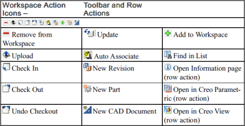
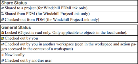
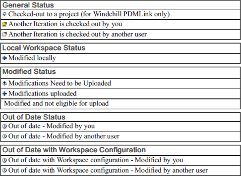
- Windchill menu commands, action icons, and status symbols used in Creo Parametric
- Some examples are provided below
Published: 28/8-2019
Reference: PTC Article - CS58783
Description
How to identify symbols that appear next to models or features in the model tree
What the symbols in front of part/feature/assembly component in the model tree mean
Explanation of icons or glyphs shown in model tree or layer tree
General information regarding the icons displayed in the model tree
What does the icon with a chain link mean?
Exclamation mark and yellow triangle symbol next to model
When can I get a chart over all model tree icons and there meaning?
Windchill PDMLink icons
- List Creo Parametric model tree icons and symbols can be found in Creo Help
- Some feature/component status glyphs
- For more info see Help Center document: Understanding Glyphs on the Model Tree
- Solid black square - Feature or model is suppressed
- Solid black square on Model or Draft note means the feature that the note is attached to is suppressed
- Hollow black square - Component is packaged in assembly
- Black square with dot inside - Component is placed with mechanism connections
- Overlapping Hollow black square - Model is a child of a packaged component
- Half filled rectangle - Feature is incomplete
- Model icon in Assembly is hollow - Part is a skeleton model
- Gray dashed square around a black cube - Component is Unplaced/Included
- Two vertical parallel lines (pause button) - Placement of the component is currently frozen
- Two vertical lines with square - feature is a child of a frozen feature
- Red exclamation mark - feature failed or component is missing (introduced in Creo Parametric 3.0)
- Yellow triangle - feature is child of failed or outdated, component is child of failed or outdated, or component contains feature with failure or outdated, see article CS196415 (introduced in Creo 3.0)
- Yellow flag - notification center, see article CS196415 (introduced in Creo 3.0)
- For more info see Help Center document: Understanding Glyphs on the Model Tree
- Components with chain link icons (there are many, one example ) indicate ATB enabled models - see article CS210510 and Help Center Model Tree Icons (A-C)
- Layer tree icons
- Hidden Items—Items temporarily hidden from the Model Tree
- Simple layers—Items are manually added to the layer
- Default layers—Created using the def_layer configuration option
- Rules Layers—Layers defined primarily with rules
- Nested Layer—Layer that primarily contains other layers
- Holds all same name layers of all components in the assembly
- Simple layer is activated (any drawing items created, shown, or pasted in the drawing are placed on the layer)
- Simple layer Isolated (Displays the selected layers and treats all non-isolated layers as hidden)
- Windchill menu commands, action icons, and status symbols used in Creo Parametric
- Some examples are provided below